KNX Analog Light Dimming
KNX is a standardized communication protocol used in home and building automation. It enables communication and central control of devices and systems in the building. KNX Analog dimmer (0-10V ) having analog control signal used to dim or control lighting fixtures, especially in building automation systems. To connect a KNX system to a 0-10V control signal, you usually need a KNX actuator or a gateway designed with an analog output. Here are the basic steps to connect a KNX system to a 0-10V control signal:
Overview:
There are various lighting control systems that work well with LED lighting. The most commonly used systems in LED lighting are DALI, 0-10V, 1-10V and DMX. Phase dimming is also used, but is less suitable for LED lighting.
With the exception of phase cut dimming, the protocol used has no impact on the light quality within the dimming range. With all these protocols, excellent dimming behavior is possible.0-10V and 1-10V are easy to understand systems and commissioning requires no specialist knowledge. However, to obtain different control groups, each group needs separate wiring. 0-10V and 1-10V do not support bi-directional communication – so if sensors are required, additional systems may be necessary.
0-10V and 1-10V are analog protocols used for dimming general lighting. Both systems use voltage levels to “communicate” with the driver.
Available in brands: Schneider , Theben, ABB, Panasonic, Hager, Gira, Ekinex, eelectron, etc.
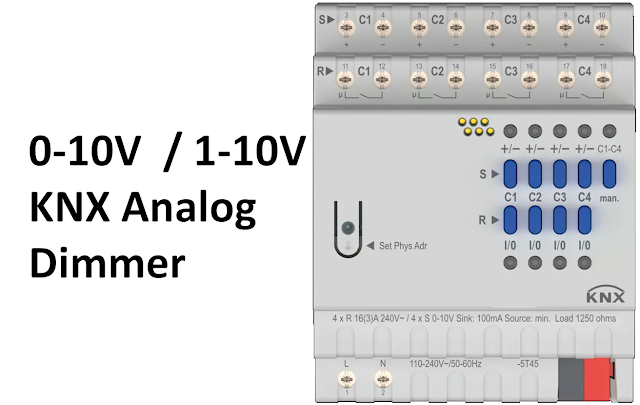
Theben SM 4 (0-10V / 1-10V Analog dimmer for KNX) As an example.

For maximum light output, a voltage of 10 V is used, and for lower light output, a lower voltage is used. But as you can see in Figure 5, between 9.1V and 10V there is no change in brightness, and between 0.5V and 1.5V there is also no change. These margins are necessary to compensate for the tolerances inherent in 0-10V and 1-10V systems. Below 0.5V the indicator goes off.

Just we proceed further, we must understand The Difference Between 0-10V And 1-10V.
0-10V and 1-10V are two different standards:
The main difference between 0-10V and 1-10V is the direction of the current between dimmer and driver.”
0-10V is a current source (ACTIVE) system, which means that the dimmer provides the power for the 0-10V signals – a mains connection to the dimmer is necessary.””1-10V is a current sink (PASSIVE) system. This means that the dimmer does not need mains power. However, to switch off the light a mains switch is necessary. Many LED drivers support a ‘light off’ function without the need of switching mains power. In above figure , this ‘light off’ function is implemented – the mains switch connections off the dimmer are also connected to the 0-10V input of the LED driver. If the mains switch is activated, the driver switches the light off.”
Advantages Of 0-10V / 1-10V Dimming:
- Traditional way of dimming, known protocol.
- No software commission needed.
- Low cost dimming method.
0-10V / 1-10V Connection:


Connect the KNX actuator to the KNX bus. The specific wiring requirements depend on your KNX installation but typically involve connecting to the KNX bus line and power supply.
Connect the 0-10V output of the KNX actuator to the 0-10V input of the dimmable device (e.g., lighting fixture). This may require a two-wire connection (positive and negative) for the 0-10V control signal.
Ensure proper grounding and polarity for the 0-10V signal to work correctly.
Device Configuration (ETS Application):
Use KNX configuration software (e.g., ETS – Engineering Tool Software) to program the KNX actuator. Assign an address to the actuator on the KNX bus, and configure its parameters.
Create group addresses or group objects within your KNX configuration that correspond to the control of the 0-10V dimmable devices. These group addresses are used to send control commands from KNX switches, sensors, or other control devices to the actuator.
Configure the actuator to respond to specific KNX group addresses and translate them into the appropriate 0-10V output levels. You may need to specify the behavior of the actuator, such as the dimming curve.


Thank You..
